- 12 Parallel SPC-150NX Modules in 19″ Case
- High-Throughput Rate
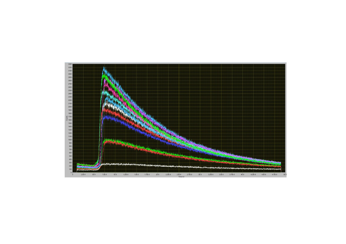
- No Crosstalk Between Channels
- Excellent Time Resolution
- Internal Timing Jitter 1.6 ps RMS (3.5 ps FWHM)
- Minimum Time Channel Width 407 ps
- Ultra-High IRF Stability
- Input Discriminator Bandwidth 4 GHz
- Saturated Count Rate 10 MHz per Channel
Specifications
|
Photon Channel |
|
|||
|
Principle |
Constant Fraction Discriminator (CFD) |
|||
|
Discriminator Input Bandwidth |
4 GHz |
|||
|
Time Resolution (FWHM/RMS, electr.) |
< 3.5 ps / 1.6 ps |
|||
|
Variance in Time of IRF centroid |
< 0.4 ps RMS over 100 s |
|||
|
Optimum Input Voltage Range |
-30 mV to -500 mV |
|||
|
Min. Input Pulse Width |
200 ps |
|||
|
Threshold |
0 to -250 mV |
|||
|
Zero Cross Adjust |
-100 mV to 100 mV |
|||
|
Synchronisation Channel |
|
|||
|
Principle |
Constant Fraction Discriminator (CFD) |
|||
|
Discriminator Input Bandwidth |
4 GHz |
|||
|
Optimum Input Voltage Range |
-30 mV to -500 mV |
|||
|
Min. Input Pulse Width |
200 ps |
|||
|
Threshold |
0 to -250 mV |
|||
|
Frequency Range |
0 to 150 MHz |
|||
|
Frequency Divider |
1, 2, 4 |
|||
|
Zero Cross Adjust |
-100 mV to 100 mV |
|||
|
Time-to-Amplitude Converters / ADCs |
|
|||
|
Principle |
Ramp Generator / Biased Amplifier |
|||
|
TAC Range |
25 ns to 2.5 µs |
|||
|
Biased Amplifier Gain |
1 to 15 |
|||
|
Biased Amplifier Offset |
0 % to 50 % of TAC Range |
|||
|
Time Range incl. Biased Amplifier |
1.67 ns to 2.5 µs |
|||
|
Min. Time Channel Width |
407 fs |
|||
|
ADC Principle |
50 ns Flash ADC with Error Correction |
|||
|
Diff. Nonlinerarity |
< 0.5 % RMS, typ. < 1 % peak-peak |
|||
|
Data Acquisition |
Histogram Mode |
|||
|
Method |
on-board multi-dim. histogramming process |
|||
|
Dead Time |
100 ns, independent of computer speed |
|||
|
Saturated Count Rate (Each Channel) |
10 MHz |
|||
|
Useful Count Rate (Each Channel) |
5 MHz |
|||
|
Max. Counts / Time Channel |
16 bits |
|||
|
Overflow Control |
none, stop, repeat and correct |
|||
|
Collection Time |
0.1 µs to 100,000 s |
|||
|
Diplay Interval Time |
10 ms to 100,000 s |
|||
|
Repeat Time |
0.1 µs to 100,000 s |
|||
|
Sequencing Recording |
Programmable Hardware Sequencer, unlimited recording by Memory swapping, in curve mode and scan mode |
|||
|
Synchronisation with Scanning |
Pixel, Line and Frame from Scanning Device |
|||
|
Routing |
7 bit, TTL |
|||
|
Experiment Trigger |
TTL |
|||
|
Data Acquisition |
FIFO / Parameter-Tag Mode |
|||
|
Method |
Time and wavelength tagging of individual photons and continuous writing to disk |
|||
|
Online Display |
Decay functions, FCS, Cross-FCS, PCH MCS Traces |
|||
|
FCS Calculation |
Multi-tau algorithm, online calculation and online fit |
|||
|
Number of counts of decay/ waveform recording |
unlimited |
|||
|
Dead Time |
100 ns |
|||
|
Saturated Count Rate, Peak (Each Channel) |
10 MHz |
|||
|
Max. Counts / Time Channel (Counting Depth) |
unlimited |
|||
|
Output Data Format (ADC / Macrotime / Routing) |
12 / 12 / 4 |
|||
|
FIFO Buffer Capacity (Photons) |
2 * 106 |
|||
|
Macro Timer Resolution, Internal Clock |
50 ns, 12 bit, overflows marked by MOTF entry in data stream |
|||
|
Input Macro Timer Resolution, Clock from Sync |
10 ns to 100 ns, 12 bit, overflow marked by MOTF entry in data stream |
|||
|
Input Curve Control (external Routing) |
4 bit, TTL |
|||
|
External Event Markers |
4 bit, TTL |
|||
|
Enable Count Control |
1 bit, TTL |
|||
|
Input Experiment Trigger |
TTL |
|||
|
Computer Interface |
|
|||
| Principle | High-Speed Parallel Interface | |||
Downloads
Documents
Gallery