

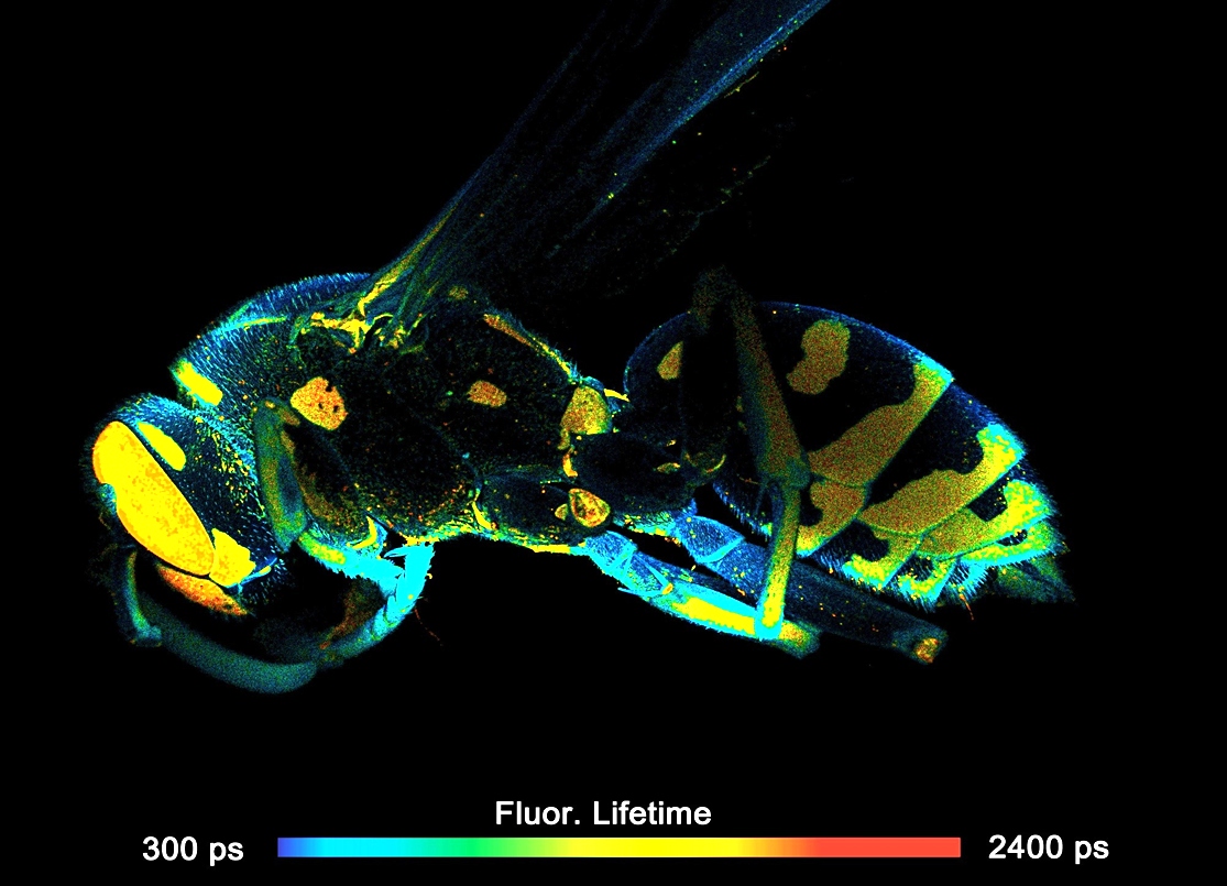
- FLIM of Macroscopic Objects
- Metabolic Imaging
- Scan Field Up to 15 mm Diameter
- UV-Enhanced Optics
- Two Fully Parallel TCSPC FLIM Channels
- Recording by bh's Multidimensional TCSPC Process
- Express FLIM Available
- Scanning by Fast Galvanometer Mirrors
- Channel Seperation by Dichroic or Polarising Beamsplitters
- Individually Selectable Pinholes and Filters
- One or Two BDL-SMN or BDS-SM ps Diode Lasers
- Tuneable Excitation by Super-Continuum Laser with AOTF
- Two Fully Parallel Confocal Detection Channels
- Two HPM-100-40 GaAsP Hybrid Detectors
- Optional: Two HPM-100-06 Hybrid Detectors, IRF Width <20 ps FWHM
- Optional: HPM-100-50 Hybrid Detectors for NIR FLIM
- Optional: Multi-Wavelength FLIM
- Excellent Time Resolution: Electrical IRF Width 3.5 ps FWHM
- Time Channel Width Down to 405 fs
- Megapixel FLIM, Up to 2048 x 2048 Pixels at 256 Time Channels
- Simultaneous FLIM / PLIM
- Wideband Version, Compatible with Tuneable Lasers
- Electronic Pinhole Alignment
- Optional: Spatial Mosaic FLIM via Motorized Sample Stage
Description
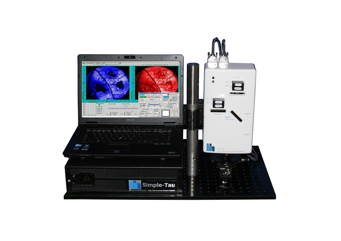
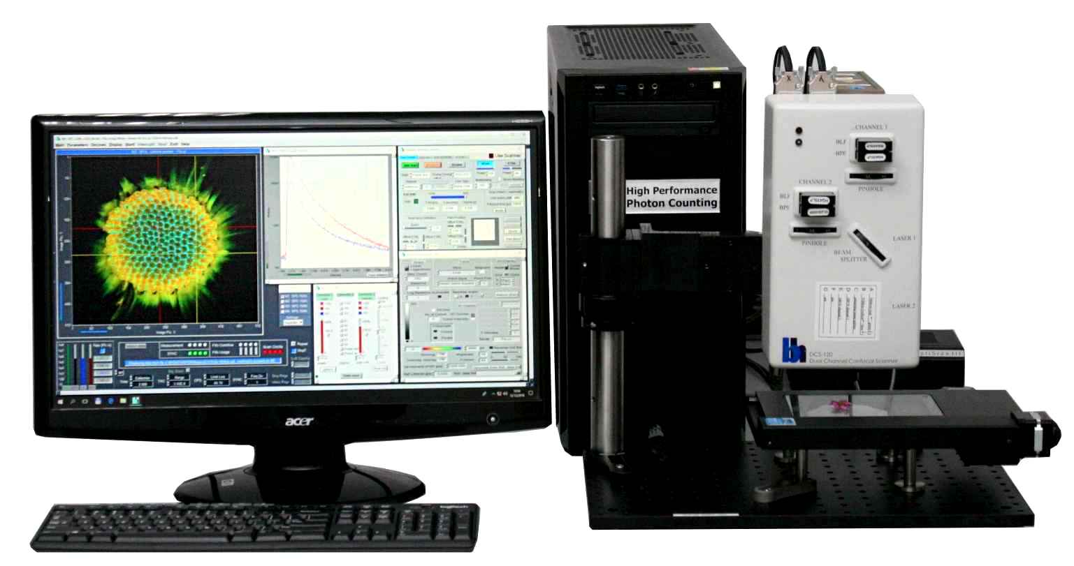
The DCS-120 MACRO version of the DCS system scans objects directly in the focal plane of the scanner. Objects up to a size of 15 mm can be imaged at a resolution of about 25 micrometers. As the DCS-120 confocal FLIM system, the DCS-120 MACRO uses excitation by ps diode lasers, fast scanning by galvanometer mirrors, confocal detection, and FLIM by bh’s multidimensional TCSPC technique to record fluorescence lifetime images at high temporal resolution, high spatial resolution, and high sensitivity. Due to its fast beam scanning and its high sensitivity the DCS-120 MACRO system is compatible with live-object imaging. DCS-120 functions include simultaneous recording of FLIM or steady-state fluorescence images simultaneously in two fully parallel wavelength channels, laser wavelength multiplexing, time-series FLIM, time-series recording, Z-Stack FLIM, phosphorescence lifetime imaging (PLIM) and fluorescence lifetime-transient scanning (FLITS) recording. Applications focus on lifetime variations by interactions of fluorophores with their molecular environment. Typical applications are ion concentration measurement, FRET experiments, metabolic imaging, imaging of fast physiological effects, and plant physiology.
Specifications
|
Selected Specifications |
||
|
Principle |
Fast galvo-mirror laser-scanning, de-scanned confocal detection (DC), and bh's multi-dimensional TCSPC FLIM technique |
|
|
Excitation |
ps pulsed lasers, fiber coupled |
|
|
Scan Rate, Pixel dwell Time |
Down to approx. 1 μs/pixel |
|
|
General Operation Modes |
TCSPC FLIM:
*with optional external sample movement hardware |
|
|
Scan Head |
||
|
Optical Principle |
Fast galvo-mirror laser-scanning |
|
|
Laser Inputs |
Two independent inputs, fiber coupled |
|
|
Optical Laser Power Control |
Continuous ND filter wheel control |
|
|
Laser Input Requirements |
Fiber coupled with 12 mm diameter collimator. |
|
|
Laser Power Regulation, Optical |
Continuously variable via neutral-density filter wheels |
|
|
Outputs to Detectors |
Two outputs, detectors are directly attached |
|
|
Main Beamsplitter Versions |
Alignment-free exchangeable dichroics: Longpass, multi-band, wideband, and multiphoton options available |
|
|
Secondary Beamsplitter Wheel |
Three dichroic beamsplitters, polarising beamsplitter, 100% to channel 1, 100% to channel 2 |
|
|
Pinholes |
Independent pinhole wheel for each channel |
|
|
Pinhole Alignment |
Electronical, via piezo microstage |
|
|
Pinhole Size |
11 pinholes, from about 0.5 to 10 AU |
|
|
Emission Filters |
Two filter sliders per channel in series |
|
|
Scan Field |
Up to 15 mm Diameter |
|
|
Scan Control |
||
|
Principle |
Hardware controlled precision laser-scanning with fast flyback for rapid acquisition |
|
|
Frame Size |
Frame scan 16 x 16 to 4096 x 4096 pixels, line scan 16 to 4096 pixels |
|
|
X Scan |
Continuous or pixel-by-pixel, |
|
|
Y Scan |
Line-by-line |
|
|
Electrical Laser Power Control |
Software control of a laser with analogue modulation input |
|
|
Laser Multiplexing |
Frame-, line-, pixel-, and intra-pixel. Requires software control of laser power. |
|
|
Beam Blanking |
During flyback and when scan is stopped. Requires software control of laser power. |
|
|
Frame Rate / Scan Speed |
Automatic selection of fastest rate or manual selection |
|
|
Scan Area Definition |
Interactive scan region selection, hardware zoom + offsets. |
|
|
Fast Preview Function |
Yes |
|
|
Beam Park Function |
Yes, interactive measurement point selection. |
|
|
TCSPC System |
||
|
TCSPC / FLIM Modules |
SPC-180NX |
SPC-QC-104 |
|
Number of Parallel TCSPC / FLIM Channels |
Typ. 2 |
Typ. 2 |
|
Electrical Time Resolution |
1.6 ps RMS / 3.5 ps FWHM |
16 ps RMS / <39 ps FWHM |
|
Timing Precision / |
1.1 ps |
11 ps |
|
Minimum Time Channel Width |
405 fs |
4 ps |
|
Saturated Count Rate |
12 MHz |
40 MHz, shared among active channels. |
|
Synchronisation with Laser Multiplexing |
Up to 4 laser wavelengths |
|
|
Recording of Multi-Wavelength Data |
Simultaneous in 16 channels, via routing function |
|
|
Experiment Trigger Function |
TTL, used for experiment start upon external signal |
|
|
Operation Modes of TCSPC System |
*with optional external sample movement hardware |
|
|
Software |
||
|
Data Acquisition Software |
bh SPCM, bh LabVIEW for integration of external devices |
|
|
Scanner Control Software |
Integrated in SPCM, bh LabVIEW for integration of external devices |
|
|
Operation System |
Windows 10 / 11 64 bit |
|
|
Data Analysis Software |
bh SPCImage NG |
|
|
Principle of Data Analysis |
MLE fit (GPU assisted processing) |
|
|
Model of Functions |
|
|
|
IRF Modelling |
Synthetic IRF function fit to decay data, auto-extraction of IRF from data, or measured IRF |
|
|
Excitation Sources |
||
|
Confocal FLIM |
One to four ps diode lasers |
|
|
Available Wavelength |
375 nm to 785 nm |
|
|
Repetition Rate |
20, 50, 80 MHz and CW |
|
|
Pulse Width |
40 ps to 100 ps |
|
|
Detectors |
||
|
Confocal Detectors |
Coupled directly to scan head |
|
|
Standard Detector |
HPM-100-40 hybrid detector with GaAsP cathode, 250 to 720 nm, best for use with ns lifetime dyes |
|
|
Optional |
HPM-100-06 detector with <20 ps FWHM IRF width, 220 to 650 nm, best for ps lifetime autofluorescence studies |
|
|
Optional |
HPM-100-50 detector, 400 to 900 nm, best for long wavelength fluorescence |
|
|
Optional |
MW-FLIM GaAsP multiwavelength detector |
|
Downloads
Documents
Datasheets
Documents
- DCS-120 Confocal and Multiphoton FLIM Systems – User Handbook 9th ed. 2021
- DCS-120 Confocal and Multiphoton FLIM Systems – Overview Brochure
- FLIM Systems for Laser Scanning Microscopes – Overview Brochure
- Bigger and Better Photons: The Road to Great FLIM Results
- SPCImage NG – Overview Brochure
- The bh FLIM Technique – More than Lifetime Imaging
The realm of the bh FLIM systems are in molecular imaging. Typical applications are the imaging of ion concentrations, pH, or local viscosity, protein interaction experiments by FRET, and metabolic imaging by fluorescence decay of NADH an FAD in combination with oxygen measurement. In these applications, the bh FLIM systems benefit from their high sensitivity, high time resolution, high timing stability, and their capability to resolve multi-exponential-decay profiles into their components. Other advantages are the capability to record FLIM of fast physiological effects down to the millisecond range, and to record at several excitation and emission wavelengths simultaneously.
Applications
Application Notes
- FLIM of Macroscopic Objects: Imaging in the Primary Image Plane of the DCS-120 Scanner
- Mosaic FLIM: New Dimensions in Fluorescence Lifetime Imaging
- Simultaneous Phosphorescence and Fluorescence Lifetime Imaging by Multi-Dimensional TCSPC and Multi-Pulse Excitation
- DCS-120 FLIM System Records X-Y Mosaics
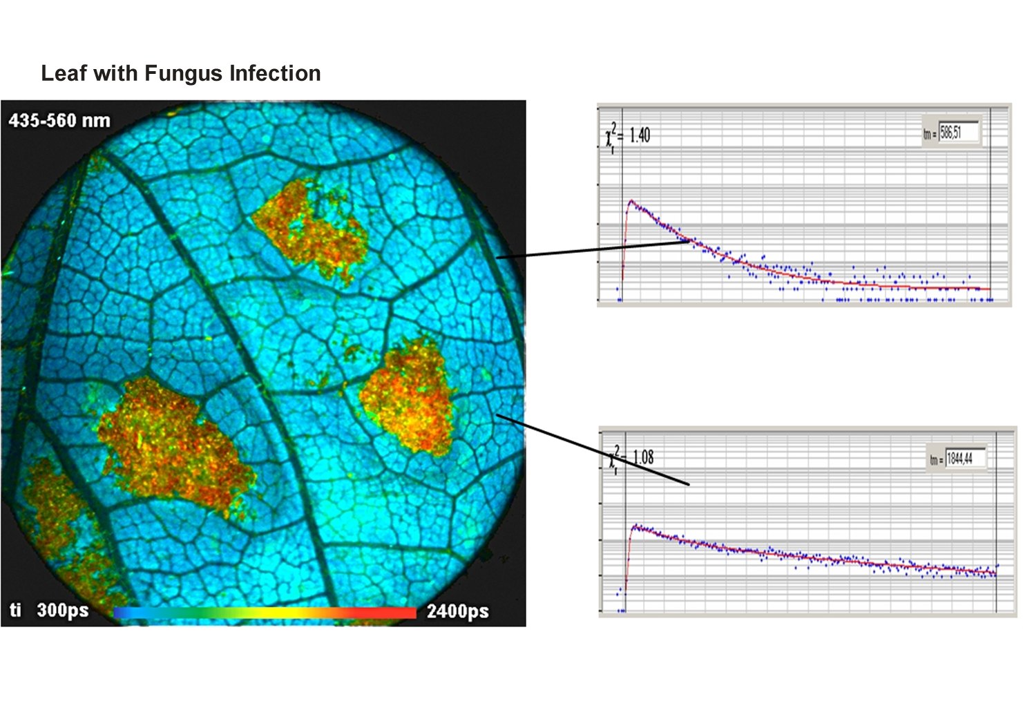
- Metabolic FLIM of Macroscopic Objects
- New SPCImage Version Combines Time-Domain Analysis with Phasor Plot
Principles
Principle of the DCS-120 MACRO System
The DCS-120 MACRO system scans macroscopic samples directly in the primary image plane of a DCS-120 confocal scan head. The principle is shown in the figure below.
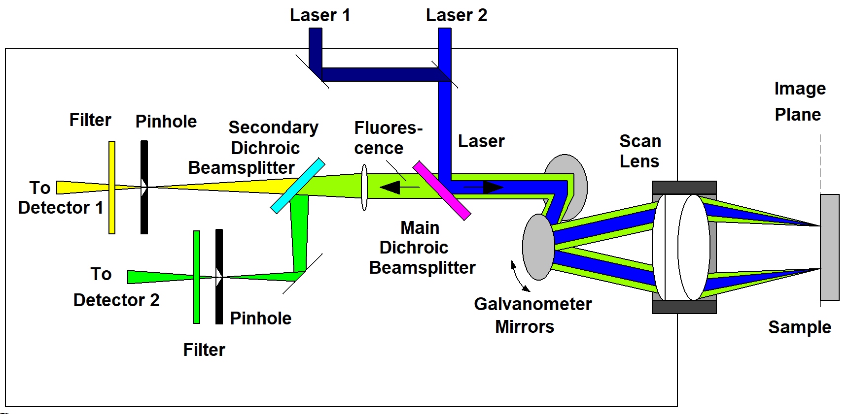
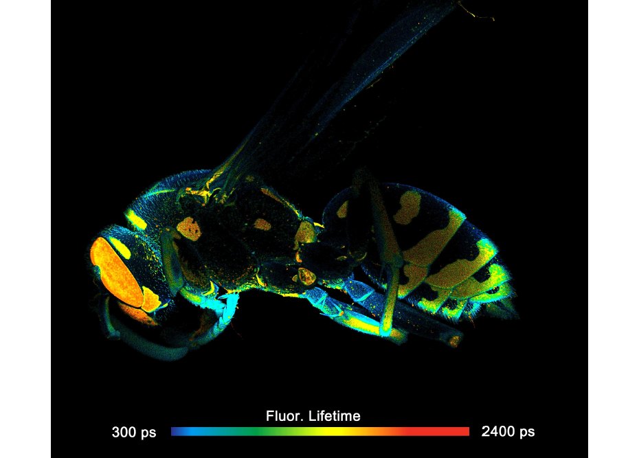
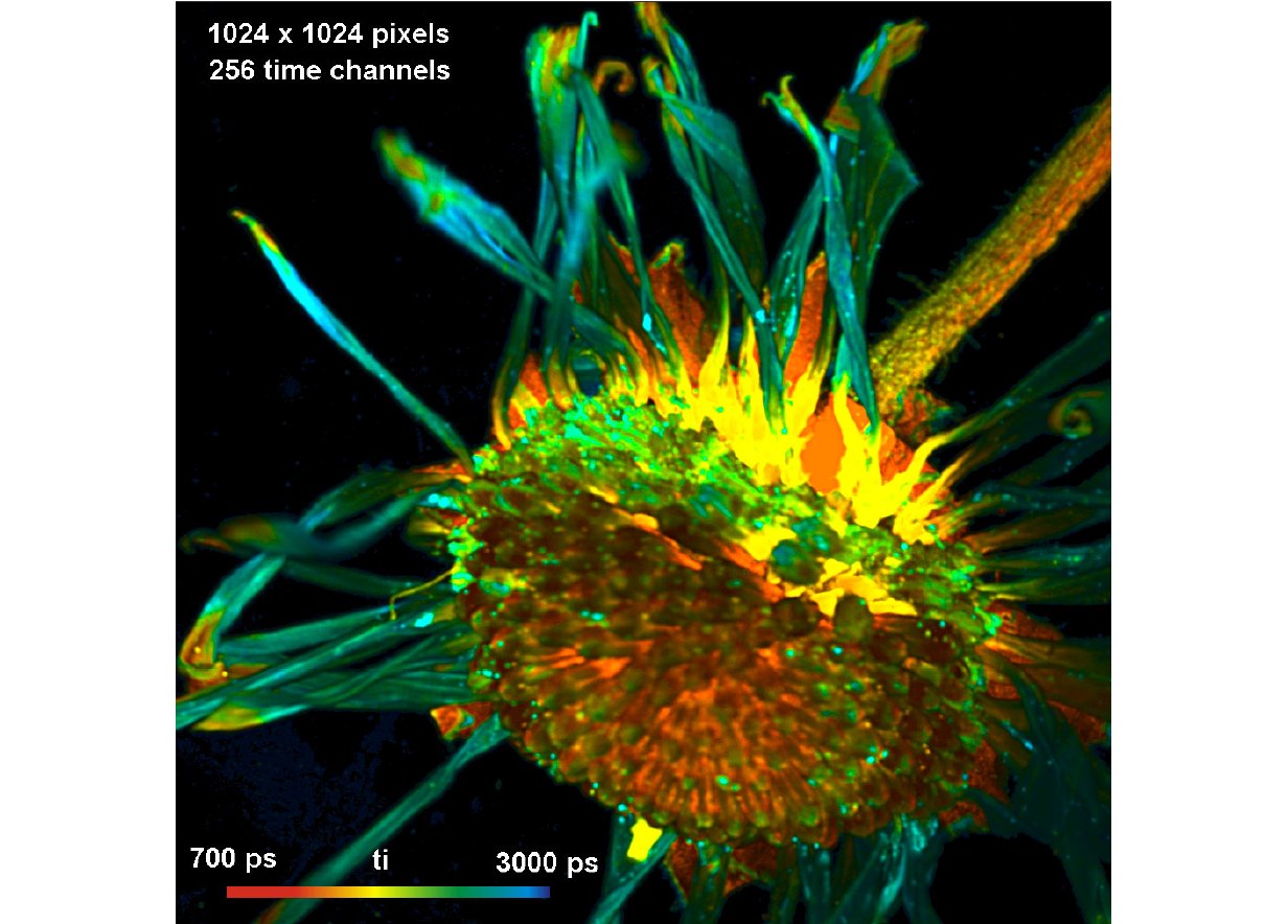
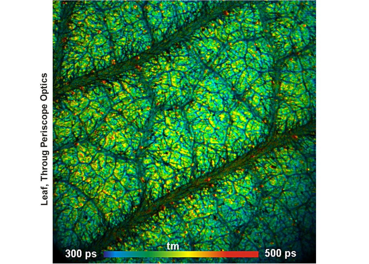
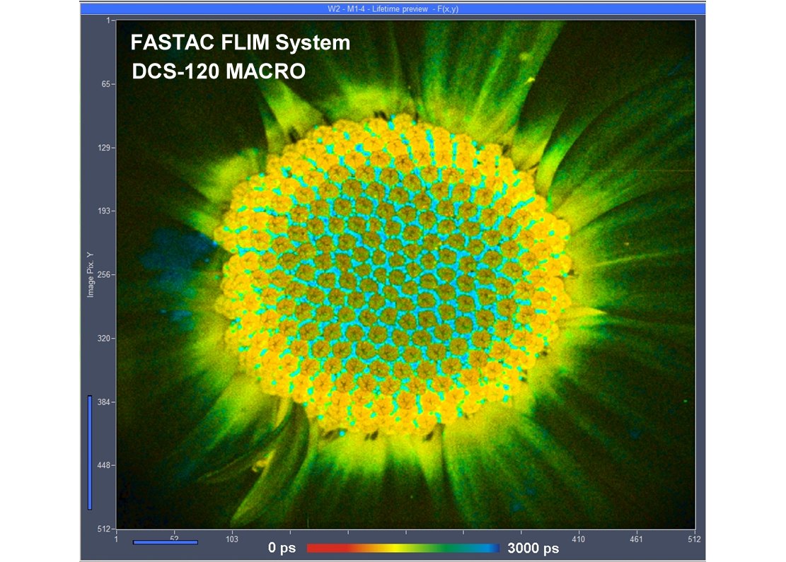
Two lasers of different wavelength are injected into the scanner via single-mode fibres. The combined laser beam is scanned by two fast-moving galvanometer mirrors. The scan lens focuses the laser beam into an image plane shortly in front of the scanner. For scanning an object, this plane is brought in coincidence with the sample surface. As the galvanometer mirrors change the beam angle the laser focus scans over the sample. Fluorescence light excited in the sample is collimated back by the scan lens, de-scanned by the galvanometer mirrors, and separated from the excitation light by the main dichroic beamsplitter. The fluorescence beam is further split into two spectral or polarisation components, and focused into pinholes. Light passing the pinholes is sent to HPM-100-40 or HPM-100-06 hybrid detectors. At maximum scan amplitude (minimum zoom), the systems scans an image area of approximately 15 x15 mm. With a spatial resolution of the DCS MACRO of about 20 micrometers, images of extremely high definition can be obtained. To fully exploit the resolution of the scanner FLIM data can be recorded with up to 20248 x 2048 pixels. The number of time channels can be selected from 64 to 4096, the recommended number is 1024. An example is shown in the figure below.
FLIM Data Acquisition
FLIM data acquisition works by bh's multi-dimensional TCSPC process. It is based on the detection of single fluorescence photons, the determination of the photon times in the laser pulse period and the location of the laser beam in the scan area in the moment of the photon detection, and the build-up of a three dimensional photon distribution over the scan coordinates and the time in the laser pulse period. Please see also Principle of the DCS-120 Confocal FLIM system.
For details please see Handbook of the DCS-120 Confocal and Multiphoton FLIM Systems and The bh TCSPC Handbook.
Gallery